Central Heating Systems Explained by Mr Central Heating! Mr Central Heating Blog
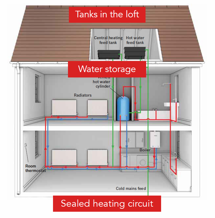
It's a closed cycle process that allows radiators to heat your home effectively.'. While the heat rises from your radiator in the form of air, the water inside becomes cooler and eventually returns to the boiler to be heated. This process is repeated as long as is needed and is typically regulated with a thermostat.

Heating System Diagram / Figure 4 6 One Pipe Hot Water Heating System Diagram This is then
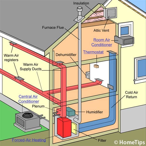
Here is the simple version: 1.Burning propane or natural gas generates heat in the furnace's burner. 2.The heat produced passes through a heat exchanger, making it hot. 3.Air from the home's ductwork is blown over the heat exchanger, warming the air. 4.The furnace's blower then forces the heated air into the supply ductwork, distributing it.

5 Schematic of a Hydronic Heating System [4] Download Scientific Diagram
A heat pump system diagram is a valuable tool not only for understanding how a heat pump works but also for performing regular maintenance and troubleshooting common issues. Regular Maintenance Tasks. Routine maintenance is vital for the optimal performance and longevity of a heat pump. Using a heat pump system diagram can help homeowners.
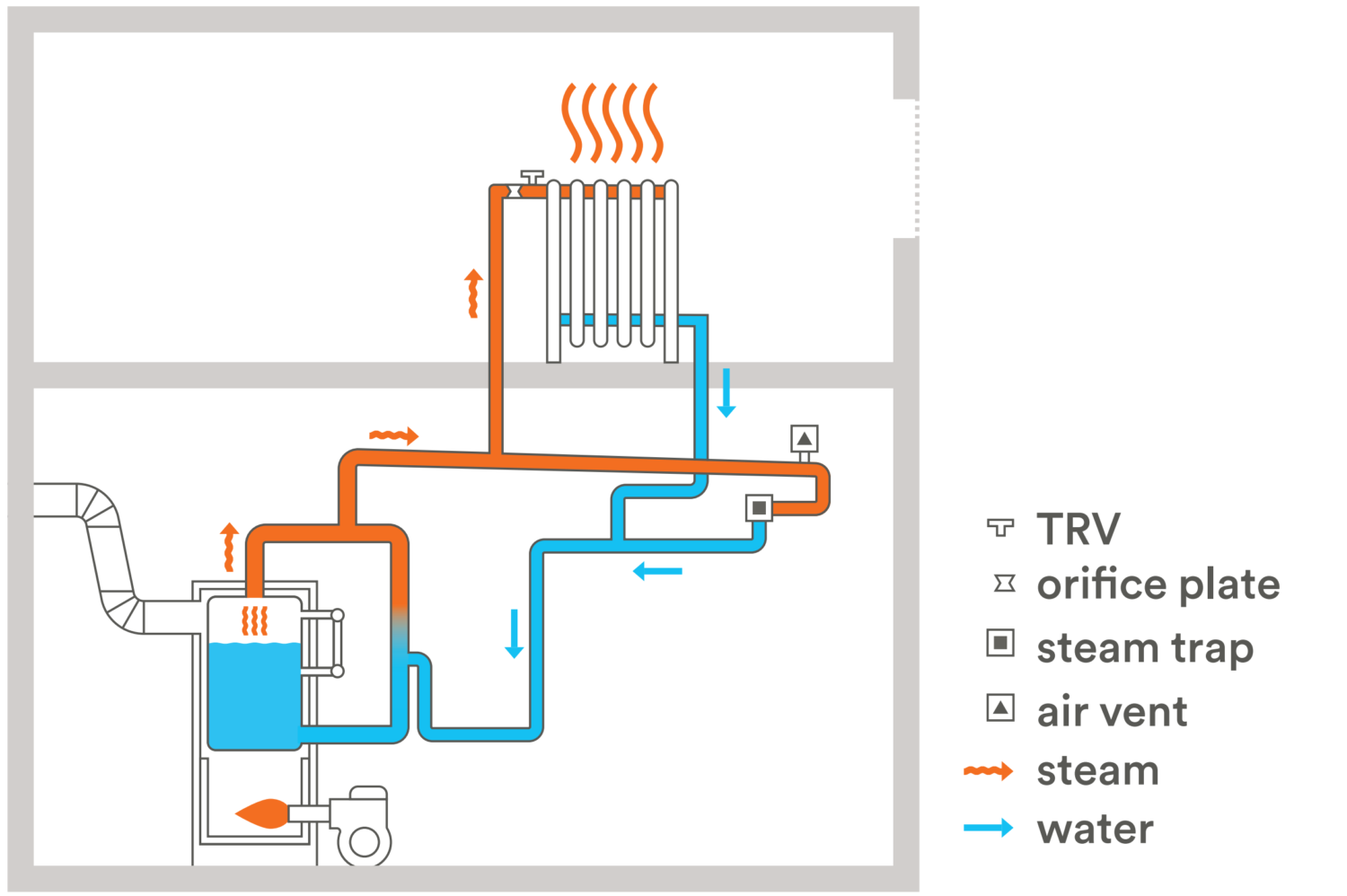
Tech Primer TwoPipe Steam Systems Building Energy Exchange
Browse 460+ heating system diagram stock illustrations and vector graphics available royalty-free, or start a new search to explore more great stock images and vector art. Detailed plumbing diagram of a two-level house, including basement, garage, ground level, upstairs level and attic. Plumbing intake line leads to hot water heater, hot and.
How Central Heating Works
The basic component of a zoned heating system is a zone valve, which controls the flow of water in a hydronic heating system. Inside the valve, an actuator opens and closes the valve based on the.
Heating Systems Explained Hounsfield Boilers
A gas water heater works by a law of physics knowns as convection— which defines how heat rises. In the case of a water heater, the cold water enters the tank through a cold water supply tube to force a constant supply of cold water into the tank.
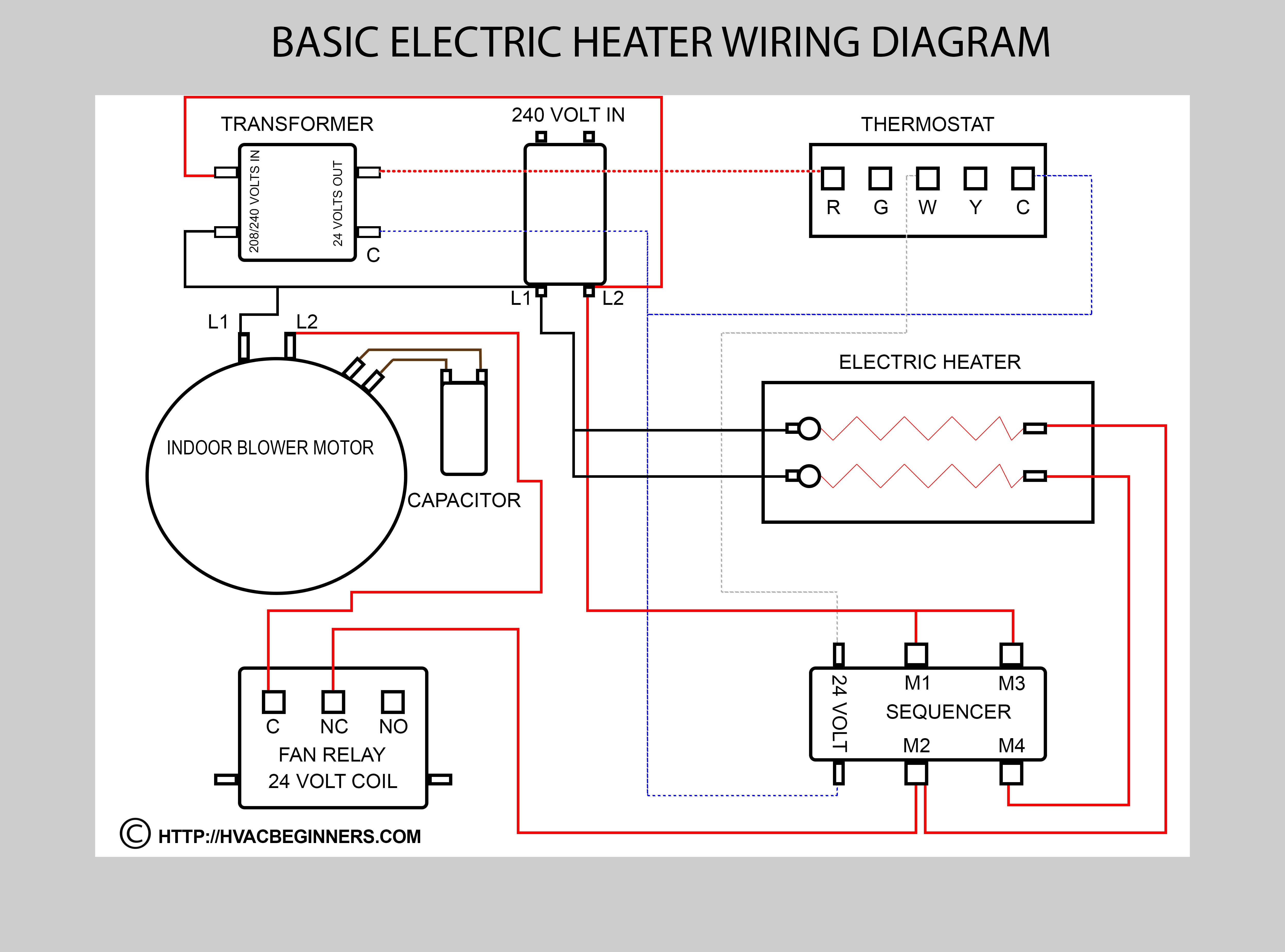
Hvac Training on Electric Heaters HVAC Training for Beginners
Install the Heater. Strip 5/8 in. of insulation from each wire's end, then connect the black and taped white wires to the black heater wires using wire connectors. Connect the cable's bare ground wire to the green heater ground wire. Push the heater into the can and fasten it. Install the cover grille.

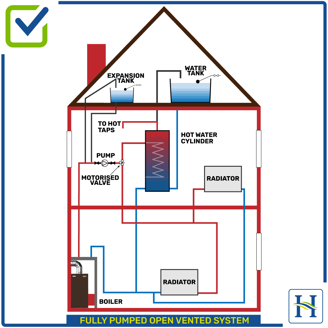
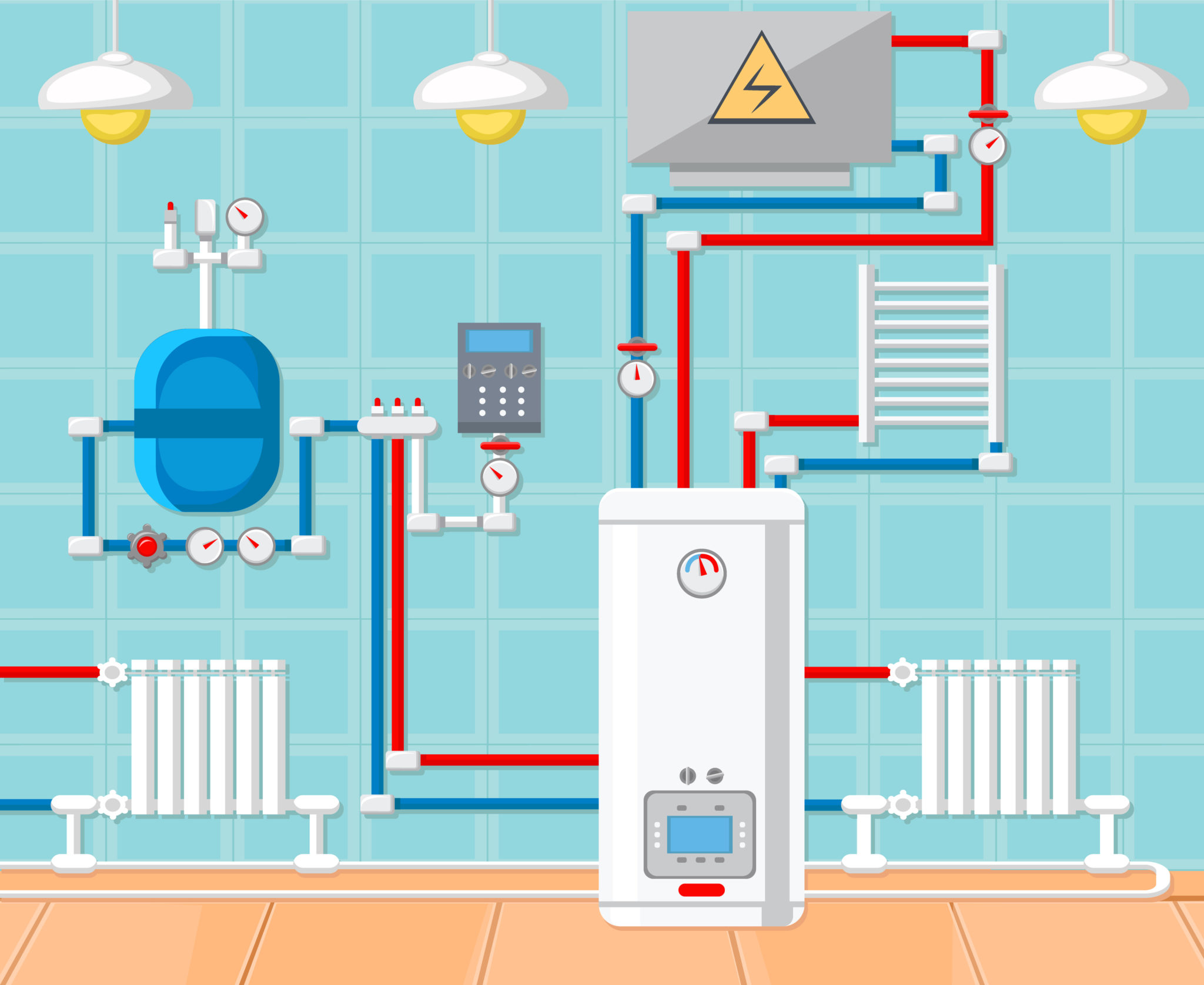
Schematic diagram of a central heating system. Download Scientific Diagram
Home central heating system diagram explained, in this case it is a diesel heater condensing gas heater.We review every thing the thermostat, the water pump,.

How your boiler and central heating system works General Scrolls
Screw the metal mounting brackets to the plywood panel, then hang the combination heater onto the brackets. Drill two 4-inch-diameter holes through the house wall for the exhaust vent and air intake vent. Be sure the air intake is above the snow line, and that the exhaust vent is 12 inches from a window and 12 inches from the air intake.

This simple diagram shows you how your HVAC system's ductwork connects, and how it functions to
How a Heater Control Valve Works (with Diagram) - In The Garage with CarParts.com The heater control valve plays a vital role in heater operation. Learn how it works in this comprehensive guide and see a sample diagram.

How Solar Water Heater Works Solar Water Heater Working Principle
Components of an HVAC System Diagram The Heart of the System: Furnace and Air Conditioner. The furnace and the air conditioner are the powerhouses of your HVAC system. They're responsible for heating and cooling the air in your home. Furnace: The furnace is the part of the system that provides heat. It does this by burning a fuel source (like.

Schematic of typical combi boiler heating and hot water system. Download Scientific Diagram
01 of 10 Forced Air Heating/Cooling Systems BanksPhotos/Getty Images Best for: Multipurpose HVAC that heats and cools quickly By far the most common HVAC system in modern North American homes, the forced air system uses a furnace with a blower fan that delivers warmed air to the various rooms of the home through a network of ducts.

Heat Hero Gravity Technical heathero.ie
G wire (fan) connected to the fan control to operate a blower in your HVAC system. Y1 wire (cooling) connected to the compressor/refrigerant system. Y2 wire (second stage cooling) connected to the 2nd stage cooling system. C wire (common) wire to complete the circuit and keep power flowing.
Heating system types how to figure out what kind of heat you have
The wiring diagram for a 3 zone heating system outlines the connections between the thermostat, zone valves, and the boiler or furnace. Each zone of the system has its own thermostat, which communicates with the zone valve to control the flow of heated water or steam to that area. The diagram shows how these components are connected and how.

Modern Central Heating
If you understand an HVAC system diagram, you can better understand what's going wrong when your vents begin to blast warm air. Keep reading to learn everything you need to know about an HVAC system diagram. What Is An HVAC System? HVAC is the system in your home responsible for Heating, Ventilating, and Air Conditioning.
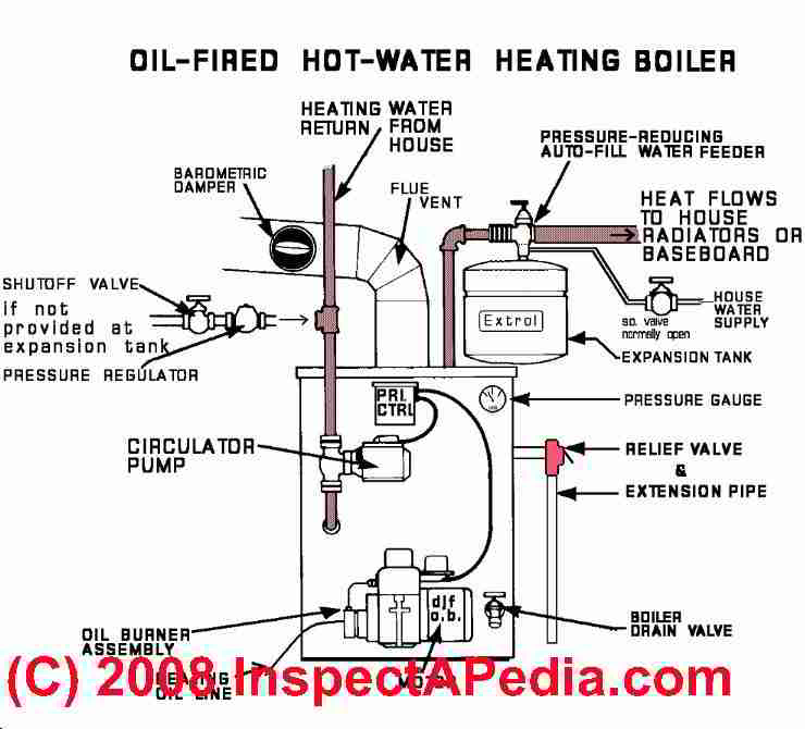
The Howto’s of a Heating System Part 1 Hot Water Heating Systems Mr Plumber
Examine the accessible parts of the heating system. Let your eye travel from component to component in the sequence of operation. at each step. Consider the implications should any component be missing, damaged, inoperative, leaky, noisy, sooty, repaired by an amateur, etc.